
Map Features
To access this panel:
-
Using the Mapping dialog, activate the Features panel.
Note: The Features panel will only appear on your system if at least one feature object has been correctly defined in your system configuration file.
Note: You can digitize face map data type using either the 3D map or butterfly map view. Butterfly maps are only available if your configuration permits it.
Face map, level map and wireframe map features are open or closed strings representing geological features. Open strings are referred to as 'contacts' and closed strings as 'outlines'. Single point data is referred to as 'points'.
The Features panel lists all features for the selected Map and Face, or loaded wireframe map. If a face map is loaded, changing the face automatically updates the contents of this panel. The design section also snaps to the appropriate face of the selected map for digitizing.
You can digitize Face map and Wireframe map features (including generating outlines) using either a 3D World or Map view of data. See Map Types.
Note: Level map data is always digitized directly into the 3D World view.
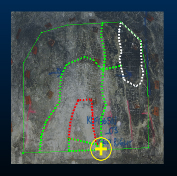
A face map showing digitized features
Adding a feature of any type to a map requires at least one Feature type to be defined in your external system configuration file. You can define as many feature types as you need.
Tip: If you are using a portable device, automatically display a screen keyboard for easier data entry at the face. Enable screen keyboard mode using the Setup ribbon's On-Screen Keyboard command.
Each feature data item can be defined using one or more attributes. Each attribute can be supported by one ore more valid values, or you can specify an absolute numeric or alphanumeric value. All attribute specification for a feature is governed by the contents of your configuration file.
Note: Default properties for custom attributes on this panel can be set in your system configuration file.
You can also create a new polygon feature using the Outlines
>> Generate
feature on the Draw (Features)
ribbon.
Calculated Fields
You can configure your system to show automatically-calculated (also known as 'virtual') data properties for a feature, such as the area of a polygon or the length of a contact string.
Feature attributes appearing as features grid columns are determined
by their corresponding <Fieldname> tag in your current configuration
file. Any supported
virtual column assignments can be specified.
Digitizing Features
Digitize a point or points on the current map face, wireframe or level to denote linear geological structures.
An outline is a closed string, referred to as a 'polygon' in Studio Mapper. Digitizing points will progressively shape the polygon. You can break an outline, although it will be labelled 'contact' in the feature properties table (see below), if you do this.
Your feature type is displayed in the features grid as either Contact, Polygon or Point. Only features for the selected object will be displayed.
The table is dynamically updated. If you are digitizing a multi-point feature (Contact or Polygon), the type is initially shown as Point, until the second and subsequent points are digitized. If you choose to digitize a Contact or Polygon and only digitize a single point, it remains a Point type.
Similarly, if you digitize a Contact and close the string by snapping the end point to the start point (or closing it using one of the editing commands), the display type automatically changes to Polygon (the reverse is true if you open a closed polygon item).
In summary: Studio Mapper recognizes the feature type you have created or edited, and assigned its type accordingly.
To digitize a feature onto a map (face, level or wireframe):
- Select a Map and Face, or a level map, or wireframe map.
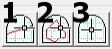
- Select either the Add Contact
(1), Add Outline (2) or
Add Point (3) button:
-
Digitize your feature directly onto the active map (see below for a note for more digitizing options) and click Done when finished.
Note: There's no need to set up snapping modes when digitizing data (say, a polygon feature) onto a wireframe map. The closest wireframe vertex or point is snapped.
Tip: Whilst digitizing, you can complete the digitizing operation by double-clicking the final string vertex position.
Each digitized contact, outline or point feature will appear in the Features table (see below). How this table is populated depends on the selection made using the drop-down list at the bottom of the panel.
- Default Fill: by default, feature attribute values will be populated using the following rules:
- If the attribute is defined as NUMERIC in your configuration file, and a range is specified, the value will be the mean average of the specified range. If no range is specified, a value of zero is set.
- If the attribute is specified as TEXT, the entry will be empty/absent to start with.
- If the attribute is specified as LOOKUP, the first specified lookup value will be set.
- Copy Previous: newly-added features will copy the previous feature attribute values.
- Blank Fill: if permitted, all attribute values will be absent for new features. Note that this is not possible if the attribute is defined as <Nullable>FALSE</Nullable> in your configuration file, in which case, the Default Fill behaviour (see above) will be applied.
The Features Table
The Features table displays a list of all independent feature entities on the currently selected map face. This list is updated if the map or face is changed.
The table displays:
- Whether the feature is currently visible or not (check box)
- The Features data object in which a feature is stored (all entities within this object will be formatted in the same way, potentially as described by your external configuration file).
- Any custom attributes and values assigned to each feature - as defined by your configuration file. These fields are editable.
- A button to delete the feature (red cross).
Note: Feature attributes can be evaluated and presented on the Map Properties panel as evaluated properties.
For example, a "Geology" feature is defined using three attributes; Lithology, Grainsize and Stratum. Lithology and Grainsize are alphanumeric and must be populated with predefined values from a drop-down list. Absent values are not allowed and the default value for each is Sandstone and VeryFine, respectively. Stratum is a numeric value between 0 and 100.
Digitizing a Geology contact adds a new entry to the Features table, containing the following columns:
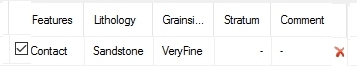
Each subsequent use of the New Contact or New Outline commands adds another entry to the table. You can hide and show features using the check box, or delete them from the current map using X.
To copy feature table rows:
You can copy and paste elements of the Features table. This can make it easier to assign a known set of common attributes to multiple features.
Copy and Paste buttons are found above the table:

-
Copy the currently selected table row to the clipboard
-
Paste the current clipboard contents into the active table row, according to the selected paste rule (see below)
Tip: If your display legend (either as defined by a template in your configuration file or manually defined in Studio Mapper) includes texture-mapped legend items, closed strings will be displayed using the assigned texture. This can be useful to highlight specific geological attributes such as rock type, blastability index, grain size and so on.
Selecting Feature Data
Feature data selection relies on string selection being enabled (it is enabled by default, if string data is loaded). You can enable or disable string selection using the Format ribbon's Select drop-down menu.
If you select feature data in the Map or 3D world view, the corresponding data object will be selected automatically in the Mapping Task Bar. The corresponding table row will also be highlighted. Conversely, if you select a table row, it is highlighted, as is the corresponding data item in the Map or 3D view.
Note: Selecting feature data from a non-current feature data object will automatically swap the Mapping task bar to show the contents of the selected data object. For example, if "Feature 1" contains a contact and is currently the active feature object, and "Feature 2" also contains a visible contact, selecting the contact in Feature 2 will swap the feature object drop-down list to show [Feature 2] and update the feature grid correspondingly.
Map Feature Editing
Level Map Features
See Level Map Features.
Wireframe Map Features
Related topics and activities